Cooling Tower Revit Files
A Revit file is a single file database that can be shared among multiple users. Plans, sections, elevations, legends, and schedules are all interconnected, and if a user makes a change in one view, the other views are automatically updated.
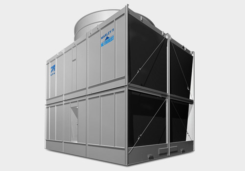
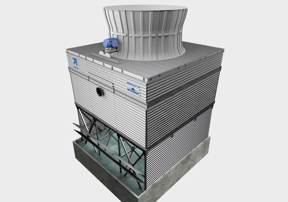
Thus, Revit drawings and schedules are always fully coordinated in terms of the building objects shown in drawings. Revit allows users to design a cooling tower and its components in 3D specifically for their building, then annotate the model with 2D drafting elements and access building information from the building models database. The Revit product family for Marley towers provides the basic geometry and typical pipe connections for each unit size of each product line. The product family covers only the product versions stated on each product’s revit information and download page. Each offering is compatible with Revit version 2009 and later.
We now offer Revit files for many of our cooling towers, with more coming soon!