Thermal Performance Testing
Overview
These are the steps necessary to conduct field and certification testing for a cooling tower. This includes site preparation for a thermal performance test. The information on this page is also provided in downloadable PDFs for printing and reference.
Preferred Test Codes
SPX Cooling Tech supports the use of the thermal test code ATC-105 published by the Cooling Technology Institute (CTI). A very similar alternative is PTC-23 published by The American Society of Mechanical Engineers. All discussion of testing assumes that one of these two codes will be followed during the test. Customers may reserve the right to specify and use modifications to these codes or elect to use another procedure. In the case of exceptions to ATC-105 or PTC-23, it is suggested that SPX Cooling Tech be consulted.
Downloads
Where customers want to use the services of third party agencies to conduct the testing, SPX supports the use of CTI Licensed Agencies. If guaranteed performance compliance is to be determined by a test, SPX Cooling will consider other agencies but reserves the right of approval. SPX Cooling reserves the right to witness any testing where contract compliance is the issue.
Types of tests
Currently, it is common to refer to tests as either Class A or B. In general, a Class A test is one conducted using mercury-in-glass thermometers and grade level psychrometers. A Class B test uses a data acquisition system and usually finds the psychrometers hung in an array over the air inlet face of the tower. This does not mean that a data acquisition system cannot be used in conjunction with grade level psychrometers. It is common to call the air temperature measurement device used in cooling tower tests a psychrometer. This is technically incorrect as a psychrometer measures the wet bulb and dry bulb temperatures while those instruments widely used today measure only a single temperature. Depending on how the “cooling tower” psychrometers are assembled, they may be used to measure either a wet or dry bulb temperature.
It is also very important to recognize the difference between an ambient and entering wet bulb test. Both ASME and CTI recommend that towers be sized and tested based on entering wet bulb temperatures. SPX Cooling also recommends that entering wet bulb temperatures be used. This consideration can affect the size of the tower selected and the results of thermal tests. An ambient wet bulb is defined as the temperature of the air mass entering the tower less any influence of the hot, moist discharge air from the tower in question (recirculation). Normally, for an ambient test at least 3 wet bulb instruments are located 50 to 100 feet upwind of the tower. It is also necessary to measure or otherwise account for the temperature and quantity of any other air streams (interference) entering the tower other than its own recirculation. This interference can come from any other source including other cooling towers. This can be very difficult to impossible in some situations. The entering wet bulb temperature attempts to measure the average temperature of all the air entering the tower regardless of its source. While this is easier than trying to separate the influence of several air masses, it still requires careful analysis by the test staff to ensure that the number of instruments and their locations are adequate.
The Typical Test
Most testing done today is conducted using data acquisition systems to measure the temperatures. This discussion assumes this type of system is used. Should mercury-in-glass thermometers be utilized, the major difference is that less data will be taken and the parameters will typically be measured sequentially.
The first order of business to conduct a test is to inspect the tower to ensure it is ready for the test and identify points of measurement for the various parameters. While the third party test agencies may consider the tower condition, it is really not their obligation to clean, balance, or otherwise adjust the tower. The customer is expected to maintain the condition of the tower and prepare it for the test. In the case of an acceptance test, the manufacturer will normally be much more thorough in this area to ensure the tower’s full potential is measured. Once this is complete and all parties are satisfied, instruments are deployed and the testing begins. This process can take from a couple of hours to one or more days usually depending on the size of the tower.
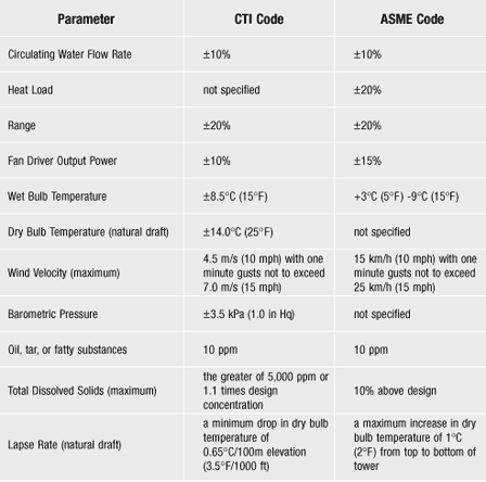
To begin the testing process, the test engineers begin taking data. Usually, the thermal data is started and monitored for a brief period. If any problems with instrumentation or conditions are noted, efforts will be made to correct them. Once this process is underway, the test staff will continue to monitor the system, and measure the water flow rate and fan power. The codes offer recommendations on deviation from design conditions for the test parameters. While it is preferable to comply with all these limitations, it is not always possible. CTI Agencies report on the deviations from recommended parameters and their history indicates only 25 – 30% of all tests find all parameters within the guidelines. Recognizing this, the codes allow for deviation provided all parties agree. If at any time during the process, it is determined a parameter is outside the recommended limitations, all parties must review the situation and reach a unanimous solution. This can result in data being discarded and restarts required. For mechanical draft towers, the actual testing process is usually one day or two days. Weather and operating conditions can sometimes increase this. For natural draft towers multiple tests over a minimum of 2 days is recommended. Due to the complex nature of natural draft tower testing, this process usually takes 3 to 5 days.
To measure the water flow rate, a pitot tube traverse of the piping carrying water to the tower is the preferred method. A wattmeter is used to measure fan input power on mechanical draft tower systems up to 600 volts. Above 600 volts alternate means must be identified. Temperatures are measure with thermometers, RTDs, or thermistors. The following parameters must always be measured: water flow rate, hot water temperature, cold water temperature, wet bulb temperature, fan power (mechanical draft towers), dry bulb temperature (natural draft towers), and wind speed. In addition, any other factor affecting the towers operation or the data taken must be accounted for. Examples may include pump discharge pressure, make-up flow and temperature, blow-down flow and temperature, auxiliary streams entering the collection basin, etc.
The hot water temperature is normally taken in the distribution basin (cross-flow towers) or in a tap in the piping carrying water to the tower. The tap may be the pitot taps, but there are times when separate taps are required. An example of this might be if the pitot taps are in underground piping and a flowing well could cause problems.
The cold water temperature is normally taken at taps on the discharge side of the pumps. In most cases, installations have pressure gauges at this location. The gauges are often replaced with flowing wells for temperature measurement. If this is not possible, separate taps need to be provided. On some towers, especially once through (helper) towers, the cold water temperature can be difficult to impossible to measure accurately. If the water discharges directly from the tower to large flumes, a lake, or a river, special consideration and instrumentation may be required. In some cases, the installation may not lend itself to accurate testing.
The codes have defined the instrumentation and procedures very clearly. Unfortunately, the many installation variations and test circumstances provide multiple obstacles. This can cause even the best of test engineers problems and increased uncertainty of results. The straightforward process alone does not protect against completely meaningless results. For this reason, the CTI carefully tests those individuals licensed by CTI to lead tests and inspects and approves their test equipment. Manufacturers also have highly skilled and trained engineers to participate in the testing process to help ensure the products are properly evaluated.
The limitation on oil, tar, fatty substances, and total dissolved solids is not routinely checked during the test process. This limitation is checked and comes into the process if a tower should fail and any party suspects these agents are present and contribute to the shortfall. Usually it is the manufacturer that requests the investigation.
Measuring the lapse rate is a complicated matter at most test sites. Both codes offer methods to estimate the lapse rate compliance. The degree to which it is pursued is usually determined by mutual agreement of methodology and normally only significant if the tower appears to be deficient. If a natural draft tower is specified for an ASME test, Marley would take exception to the outdated ASME lapse rate restriction, and refer to the more current CTI ATC-105 requirements.
One or more identical cells of a multi-cell tower may be shut down during the test if necessary, to conform with the limitations in the table shown below. This test is then considered representative of the whole tower. Both codes allow this.
It is not always possible for all parameters to be within the recommended limitations. A test is considered valid if all parties agree that one or more parameters may be outside these limits.
Site Preparation for a Thermal Performance Test
For a thermal performance test, especially an acceptance test, there are certain site requirements that need to be met by the customer or his representative. The following list includes the common considerations for a standard tower installation operating on a closed loop system. Some tower installations due to their unique installation and/or application may modify this list. If there is any question, please contact SPX Cooling Technologies’ Field and Certification Testing Services Department.
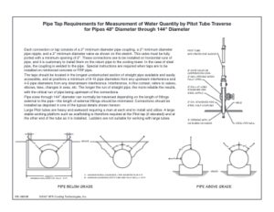
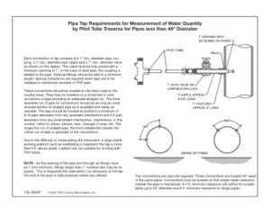
Pitot tube taps in the pipe(s) delivering water to the cooling tower. These taps should conform to the pitot tap instructions (see below). While SPX Cooling Tech’s instructions show the break point for larger taps at pipes over 48 inches, one could use the larger taps in pipes down to 30 inches in diameter. The larger taps accommodate reinforced pitot rods designed to minimize vibration effects on the measurement of flow. It is less expensive to include the taps in the original pipe installation. If a new project is to include an acceptance test, we suggest the piping contractor include the taps during the original installation.
Taps should be installed for measurement of water temperatures if required. Hot water temperature can normally be measured in the distribution basin of crossflow towers. Often the pitot taps can also be a measurement point for hot water temperature. If site specific circumstances make neither of these options acceptable, special taps will be required. The cold water temperature is normally accomplished at the discharge of the circulating water pumps. The most common location is at the pressure gauge tap present on most systems. If this is not available or applicable on a system, special taps or another solution must be identified. Measurement in a tower basin is not acceptable. Measurement of cold water temperature in a flume or channel can sometimes be accomplished with acceptable accuracy, but specifics should be reviewed.
At the time of the test, safe access to any elevated points of measurement must be provided. Examples would be pitot tube taps, hot water measurement taps, etc. All access must conform to safe work practices, OSHA requirements, and any local plant requirements. Especially in the case of pitot tube taps, the access must be scaffolding or a multi-person manlift. This work cannot be accomplished from ladders.
Power for test instruments available adjacent to the tower. This should be single phase, 110 volt, 50 or 60 cycle. On very large towers multiple sources around the tower are preferable to reduce the amount of extension cord and resulting line loss.
The tower should be ready for testing before the test engineers arrive. The following considerations are important to evaluate the full capability of any tower:
- Towers with PVC film-fill should be operated at design water flow and heat load for 1000 hours prior to doing a performance test. The reason for this is to wash lubricants from the surface of the fill used in the production of the PVC. These lubricants inhibit the wetability, and heat transfer capability of the fill. For additional information refer to the Cooling Technology Institute paper TP00-01 – “Design Features of Cross-Fluted Film Fill and Their Effect on Thermal Performance” by Rich Aull and Tim Krell on fill aging (sometimes referred to as seasoning). Their work shows that film fill requires about 2 to 3 weeks of seasoning in their “aging tank”—they indicate that one week in the aging tank was equal to about four weeks of tower operation, which means about 8 weeks (1344 hours) of seasoning time in the tower to get the full capacity of the fill performance.
- The tower should be clean. The distribution system should not have any damaged, missing, or plugged nozzles or orifices. The distribution system should be balanced as well as the design allows. The air inlet should be cleared of any blockage. If the tower has louvers, they should be in the normal design position, if adjustable. The eliminators should be free of foreign matter. Fan discharge should be clear and unobstructed.
- Water flow and heat load to the tower or representative cells, should be as close to design as the system will permit. If the code recommended limitations cannot be met, all parties should review the situation to agree on the deviation or delay/cancel the test.
- Any water bypasses should be closed and inspected to ensure there is no leakage.
- Any source of air leakage should be closed/blocked. Examples: access doors, mechanical equipment supports, or holes in the casing or fan cylinders.
- A mechanical draft tower must be operated with all fans operating on full speed forward. They must not cycle during the test period. In the case of tower fans operating on VFD’s, they should be placed in by-pass mode if the systems allows this.
- The owner or his representative should designate a coordinator qualified to integrate the testing activity and the normal process operation being served by the cooling tower. Operators of the system should be notified in advance of the testing activity.
- An electrician or qualified operator should be available to assist in the measurement of fan power on mechanical draft towers. A wattmeter is normally used to measure fan motor power at the starters or other suitable location. If the power supply is over 600 volts or drive is not electrical, another method acceptable to all parties should be identified to measure this parameter.
- All parties to the test should be advised in advance of any special safety issues required at the site. This includes training, equipment, testing, or restrictions. Marley is committed to safety in the workplace and will ensure its employees and subcontractors comply with all rules and regulations.

