Variable Flow Over Cooling Towers
There are significant energy savings opportunities if a cooling tower can be operated under variable flow conditions. Varying the flow rate over the cooling tower, not through the process the cooling tower serves has no effect on process efficiency, as the process is still allowed to operate in its most efficient manner.
Variable flow is a way to maximize the effectiveness of the installed cooling tower capacity for whatever flow the process has.
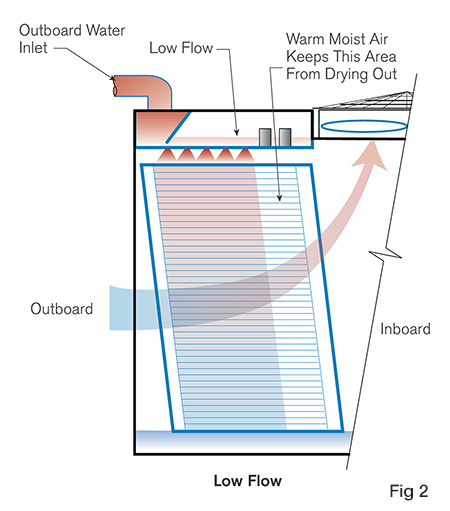
What if the cooling tower could be operated over reduced flow conditions, so that 75% of the flow that’s going through the three operating chillers is put over all four cooling tower cells. See Figure 1.
Do not the change chiller’s operation, chillers should still operate in their most efficient manner. Instead continually use all the available water flow (75% of design) in all four cooling tower cells. Continue to use the entire installed wetted surface so each cooling tower cell receives 75% of the designated water flow.
Running all four fans at 75% speed will produce the same cooling capacity as running three fans at full speed. Taking advantage of the fan laws ensure that the fans running at 75% speed draw only 42% of the horsepower or just under 17 bhp each for a total of 68 bhp for all fans. Note that drawing 120 bhp by running three fans at full speed is the traditional method, however, it is not as efficient. Forty-four percent of the fan energy can be saved by circulating 75% flow over all of the cooling tower cells if proper water distribution can be achieved within the cooling towers.
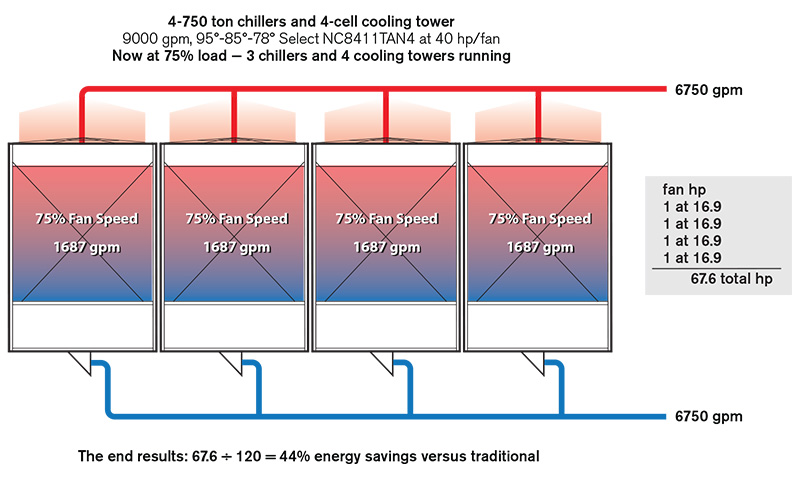
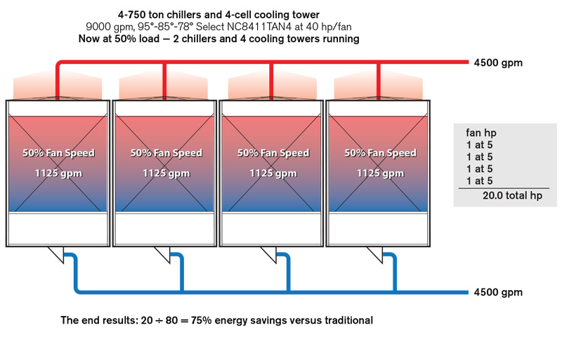
Next, if the cooling towers are able to circulate 50% flow with good water distribution, running all four cooling towers when only operating two chillers and two condenser water pumps should work. In this scenario running all four fans at half speed provides the same cooling with the same capacity as running two fans at full speed but because of the fan laws the total brake horsepower drops to 20, 5 hp per fan times four fans, compared to 80 hp for running two fans at full speed. Potentially 75% of the fan energy can be saved, if proper water distribution can be achieved within the cooling towers.
As in the earlier example, trading wetted surface for fan horsepower saves energy. Simple modifications to Marley crossflow cooling towers permit variance in the flow rate over a wide range by varying the number of nozzles that are active as a function of the flow rate.
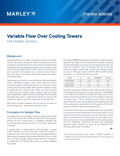
Installing Variflow nozzle cups can effectively divide the hot water distribution basin into outboard and inboard sections. This allows the cooling tower to manage variations in flow automatically, ensuring that adequate head over the active nozzles is maintained. Most importantly, uniform air side pressure drop is maintained across the fill.
Reducing the flow to the minimum flow rate as in the following graphic results in the head in the basin dropping and the Variflow cups becoming fully active. This completely cuts off water flow to the nozzles on the inboard side of the basin. The nozzles at the rear of the basin are now dry. When the process the cooling towers are serving is operating at reduced load, Variflow nozzle cups help provide consistent off-design performance and increased energy saving when operating cooling towers with lower fan speeds.
Learn more by downloading the SPX Variable Flow whitepaper: